CNC (Computer Numerical Control) machines have revolutionized the manufacturing industry, enabling precise and efficient production of intricate components and products. One crucial aspect of operating CNC machines is understanding the file formats they utilize. In this article, we will explore the various types of files CNC machines use and delve into their significance in achieving optimal machining results.
Three Distinct CAD File Types for Varied Modeling Needs
Now that you are acquainted with the most prevalent CAD file formats, it is crucial to recognize that CAD files can be further classified into three main types:
- Solid Modeling: Tailored for 3D objects requiring stability, this type incorporates specialized mathematical considerations for mass, center of gravity, and inertia. Objects can be combined or subtracted, allowing for intricate design manipulations;
- Surface Modeling: Designed for external surface projects where mass or volume considerations are unnecessary. Unlike solid modeling, objects in this category cannot be joined or subtracted, making it ideal for aesthetically focused designs;
- Mesh Modeling: Similar to solid modeling but devoid of mass considerations, this type permits shaping objects in exceptionally unique ways. Mesh modeling allows for unparalleled creativity, not feasible in solid or surface modeling.
As CNC projects evolve, they often necessitate various modeling techniques during different developmental stages, resulting in the requirement for distinct CAD files at each step. A proficient CNC studio is well-versed in determining the most suitable files for each modeling phase and adeptly orchestrates conversions to new formats at the opportune moments.
Native File Formats: Catering to Specific Machines
Native file formats play a crucial role in catering to the specific needs of various CNC machines, as they enable a seamless communication channel between the design software and the machine’s controller. Different CNC machines have their own preferred native file formats, allowing them to directly interpret and execute the unique instructions they require for precise machining operations.
For instance, Vectric software utilizes the CRV3D file format, tailored to seamlessly integrate with certain CNC machines. This format ensures that the intricate details of the design are accurately communicated to the machine, resulting in a flawless manufacturing process.
Similarly, Heidenhain controllers rely on the NC file format, specially designed to accommodate their particular set of commands and parameters. By using the NC format, these controllers can effortlessly decipher the instructions, enabling smooth and efficient machining with minimal room for errors.
By adapting to these machine-specific native file formats, manufacturers and CNC operators can harness the full potential of their equipment, unlocking enhanced performance and optimal results. This level of compatibility streamlines the production workflow, fosters precision, and ultimately boosts productivity, empowering businesses to stay competitive in the ever-evolving manufacturing landscape. As technology continues to progress, the significance of native file formats in driving seamless interactions between design software and CNC machines will only grow, revolutionizing the manufacturing industry.
Post-Processors: Adapting to Machine-Specific Code
Post-processors play a vital role in the CNC machining workflow by serving as a bridge between CAM software and the diverse array of CNC machine brands and models available in the market. Their key function is to take the output generated by CAM software, which contains the toolpaths and instructions for machining a specific part, and translate it into machine-specific G-code.
Each CNC machine has its own unique language, often referred to as a “dialect” of G-code. This dialect is a set of machine-specific commands and parameters that the machine understands and can execute. Without post-processors, CNC machines would not be able to interpret the standardized G-code output directly from CAM software, leading to compatibility issues and rendering the entire manufacturing process unworkable.
Post-processors, however, act as adaptable linguists, capable of converting the CAM output into the precise G-code dialect that each machine understands. This adaptability allows manufacturers to seamlessly switch between different CNC machines without the need for extensive reprogramming or adjustments.
Furthermore, post-processors can be customized or fine-tuned to optimize the machining process for specific machines, taking into account their unique capabilities and performance characteristics. This level of customization ensures that each CNC machine operates at its full potential, delivering the highest quality results and maximizing efficiency.
As CNC technology continues to advance and new machines with different capabilities emerge, post-processors remain a critical component in the CNC machining ecosystem. They provide the flexibility and versatility needed to keep up with the ever-expanding range of CNC machines, enabling manufacturers to harness the full power of their equipment and stay at the forefront of the manufacturing industry. With the continuous evolution of post-processor technology, the seamless adaptation of CAM output to machine-specific code will continue to drive innovation and productivity in CNC machining processes.
Understanding Toolpath Files
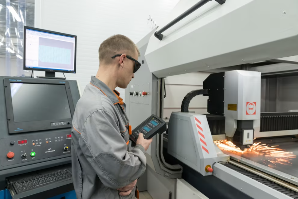
Toolpath files play a fundamental role in CNC machining, serving as essential intermediaries that contain crucial information about the tool’s movements, cutting strategies, speeds, and feeds during the entire machining process. These files act as a roadmap that guides the CNC machine in executing precise and intricate operations on the workpiece.
Within a toolpath file, intricate details are encoded, such as the tool’s position, the direction it should move, the depth of each cut, and the desired tool engagement with the material. The file also includes data on the spindle speed and feed rates, determining how fast the tool should rotate and advance through the material. Additionally, information about tool changes, tool offsets, and tool compensation may be incorporated to accommodate various tooling configurations and enhance machining accuracy.
One of the significant advantages of toolpath files is their versatility across different CNC machines and CAM software. These files use standardized formats, such as G-code or other CNC-specific languages, making them universally understandable by various CNC controllers. As a result, manufacturers can seamlessly transfer toolpath files between different machines, ensuring consistent and repeatable results regardless of the specific CNC equipment used.
Furthermore, toolpath files are not limited to simple linear or circular movements; they can be highly sophisticated, incorporating complex 3D toolpaths for intricate part geometries. This level of sophistication enables CNC machines to produce intricate designs and intricate parts with exceptional precision and efficiency.
Understanding toolpath files is essential for CNC programmers and operators as it allows them to analyze, optimize, and simulate the machining process before physically cutting the material. This simulation capability helps detect potential issues, such as collisions or excessive tool deflection, which can be corrected before the actual machining begins, saving valuable time and resources.
Simulation Software: Verifying CNC Programs
Simulation software has become an invaluable tool in the realm of CNC machining, revolutionizing the way CNC programs are developed and validated. This powerful software enables users to go beyond mere lines of code and step into a virtual realm where they can visualize and thoroughly verify the entire machining process before a single chip is cut. This capability brings numerous benefits to manufacturers and CNC operators alike.
By utilizing simulation software, CNC programmers can gain valuable insights into how the toolpaths will be executed, how the cutting tool will interact with the material, and how the part will take shape during the manufacturing process. This virtual representation allows them to identify potential issues, such as collisions between the tool and the part or fixture, as well as detect any inaccuracies in the toolpath that may compromise the final product’s quality.
Cloud-Based File Sharing: Collaborating Seamlessly
Cloud-based file sharing has transformed the way CNC projects are executed by fostering seamless collaboration among team members. These innovative platforms provide a centralized and accessible space where design files, toolpaths, and other project-related data can be securely stored and shared.
With cloud-based file sharing, team members can work together in real-time, regardless of their geographical locations. This level of connectivity breaks down barriers and enables efficient communication, as changes and updates to project files are instantly visible to all authorized individuals. This synchronous collaboration streamlines the entire workflow, reducing delays and ensuring that everyone is on the same page.
CAD Files for CNC Services
CAD files play a crucial role in CNC (Computer Numerical Control) projects, serving as 2D or 3D representations of the final design. They offer a quicker and more efficient way to visualize and make modifications, eliminating the need for physical prototypes for each iteration.
The common CAD file types used for CNC machines include:
| File Format | Description | Compatible Software |
|---|---|---|
| STEP (.stp) | Widely accepted CAD format for creating shapes and forms, ideal for CNC routers executing 3D carving. | AutoCAD, FreeCAD, ABViewer, TurboCAD, CATIA, IDA-STEP |
| STL | Unique representation of 3D models with discretized surface geometry, commonly used for 3D printing and additive manufacturing. | Microsoft 3D Viewer, Microsoft Print 3D, IMSI TurboCAD Pro, MeshLab, etc. |
| ZBrush (.zpr, .ztl) | Powerful software for 3D sculpture fabrication, video game development, and digital effects in movies. | ZBrush program |
| MAX (.max) | Capable of rendering photorealistic 3D images and animations with complex camera, lighting, material, and textural information. | Autodesk 3Ds Max software |
| Maya (.ma) | Ideal for creating 3D scenes in movies and video games, utilizing ASCII format for universal compatibility. | Autodesk Maya |
| SketchUp (.skp) | Beginner-friendly 3D modeler, commonly used for initial CNC projects. | SketchUp software |
| IGES | Oldest type of CAD file, lacks comprehensive geometric information, often replaced by STEP files for enhanced capabilities. | Autodesk Fusion 360, ideaMK IGSViewer, CADSoftTools, ABViewer |
| DXF | Versatile file format for laser cutting CNC services, translating designs into machine-readable instructions. | AutoCAD, DWG TrueView |
These file formats facilitate seamless communication between CAD software and CNC machines, ensuring accurate and precise manufacturing outcomes.
Opening CAD Files
AutoCAD provides a seamless way to open CAD files effortlessly. However, depending on the type of CAD file, other programs can also be used for opening them. If needed, you can convert CAD files to make them accessible by other software, but keep in mind that some information may be lost during the conversion process.

Preserving CAD File Integrity: To Convert or Not?
When facing difficulty opening a CAD file, it’s advisable to send the original file directly to your CNC studio instead of resorting to conversion. Converting CAD files may lead to the loss or alteration of crucial information, potentially impacting the accuracy and visual representation of the design.
For instance, converting an .stp file might result in the loss of textures, which can be vital for distinguishing different surface materials in a floorplan. If a floorplan is originally saved as a .max file and converted to an .stp file, important textures depicting concrete, brick, stone, and other materials may be compromised. By relying on a proficient CNC studio, you ensure the proper conversion of CAD files into the most appropriate format without sacrificing essential information, safeguarding the integrity of your designs.
Preparing Your CAD Files for Instant CNC Pricing
As a design engineer, leveraging AI-powered digital manufacturing supply chains can significantly enhance your productivity. Assuming your design is already optimized for CNC machining, the subsequent steps are straightforward yet vital to ensure seamless execution:
Step 1: Exporting your models in a CNC-Compatible Format
For CNC machining, predominant file formats include STEP and IGES, widely recognized and standardized for cross-platform use. Additionally, certain manufacturing services accept 3D models in formats like SLDPRT, 3DM, IPT, SAT, and X_T.
To maintain precision and avoid conversion errors, it is advisable to export your designs directly as STEP files from your native CAD software before uploading them.
Step 2: Creating a Technical Drawing for CNC Machining
Modern CNC machining systems have advanced capabilities that allow them to directly interpret part geometry from 3D CAD files or receive G-code output from CAM software. This means that a 2D drawing is not always essential for manufacturing a part using CNC machining.
However, despite this, it is highly advisable to include a technical drawing when placing your CNC order, as it provides additional information not present in a STEP file. A technical drawing becomes particularly necessary in the following situations:
- When your design incorporates threaded features;
- When you define specific tolerances and critical dimensions;
- When certain surfaces require precise finishing.
Even if your design doesn’t contain these elements, it remains a good practice to include a 2D drawing when working with CNC machining. In fact, many CNC machinists prefer technical drawings over 3D CAD files for several reasons:
- It simplifies the identification of key dimensions, functionalities, and critical features of the part;
- It aids in assessing the machining operations required for manufacturing the part;
- In the event of any dispute, the technical drawing serves as the definitive reference.
Pro Tip: While the example drawing above shows the model as fully dimensioned, it is not essential to include all dimensions in your CNC machining order. Since the dimensions are already conveyed in the 3D CAD file, you can save time by annotating only the most crucial dimensions that you want the manufacturer to verify (along with any threads, tolerances, or surface finishes).
If you wish to learn more about preparing a technical drawing for CNC machining, a detailed step-by-step guide is available. To summarize the key steps you should follow:
- Determine and present the most important views of the part;
- Consider adding section views if the part has hidden geometries;
- Incorporate construction lines such as center lines, center marks, and center mark patterns;
- Add dimensions, starting with the most critical ones;
- Clearly specify the exact location and dimensions of all threads;
- Include tolerances (if not specified, the standard tolerance will be ±0.125 mm or ±0.005 in);
- Complete the title block and include relevant notes for the manufacturer.
Step 3: Obtain an Online CNC Machining Quote
Thanks to online manufacturing networks, sourcing CNC machined parts has become remarkably convenient. To receive an instant quote, simply follow these straightforward steps: upload your files, select the desired material, quantity, and lead time, and specify any additional manufacturing requirements.
By leveraging this technology, companies can significantly save time and costs, gaining a competitive advantage. In a rapidly advancing technological landscape, the ability to adapt swiftly to change will be the key to success, surpassing the traditional notion of strength or size as the primary factors for thriving businesses.
Conclusion
Comprehending the various file formats utilized by CNC machines is vital for achieving precision and efficiency in the manufacturing process. From the foundational G-code to the versatile STL and interoperable STEP and IGES, each format plays a critical role in converting designs into tangible products. As CNC technology continues to advance, staying up-to-date with evolving file formats and software is crucial for maximizing the potential of these powerful machines in modern manufacturing.
